
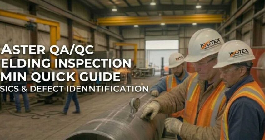
Professional QA/QC Welding Inspection, Quality Assurance (QA) and Quality Control (QC) are the backbone of structural integrity, piping, and industrial fabrication. This concise 5-minute guide breaks down the essential concepts, inspection procedures, common defects, and non-destructive testing (NDT) methods every inspector and engineer should know.
Lesson 1: QA vs QC Welding Inspector Responsibilities
While often used interchangeably, QA/QC Welding Inspectior serve two distinct functions within industrial manufacturing and construction.
1-Quality Assurance (QA): A preventive process focused on the system and procedures. QA establishes Standards, Standard Operating Procedures (SOPs), and quality plans to ensure defects do not occur during execution.
2-Quality Control (QC): A corrective process focused on the actual product. QC involves physical inspection, testing, and measurements to identify and rectify defects in the finished weld or component.
3-Key Responsibilities of a Welding QC Inspector:
a. Review engineering drawings, Welding Procedure Specifications (WPS), and Procedure Qualification Records (PQR).
b. Verify welder qualifications and certifications (Welder Performance Qualification – WPQ).
c. Inspect raw materials, base metals, and filler wires for compliance before fabrication begins.
d. Perform visual inspections before, during, and after the welding process.
4-Applicable Codes and International Standards
QA/QC welding inspection procedures and acceptance criteria are governed by globally recognized international standards:
- ASME Section IX: Welding, Brazing, and Fusing Qualifications (Boilers & Pressure Vessels).
- AWS D1.1: Structural Welding Code – Steel (Structural & Construction Safety).
- API 1104: Welding of Pipelines and Related Facilities (Cross-country Oil & Gas Pipelines).
- ASME B31.3: Process Piping Code (Refineries
Lesson 2: Common Welding Defects & Causes
Identifying welding flaws early prevents catastrophic structural failures. Below are the most common welding defects, their visual characteristics, and root causes:
| Defect | Visual Description | Root Cause |
|---|---|---|
| Porosity | Small gas pockets or cavities trapped inside or on the surface of the weld. | Shielding gas contamination, excessive draft, moisture, or rusty electrode/base metal. |
| Cracks | Linear fractures along the weld bead, heat-affected zone (HAZ), or base metal. | Rapid cooling rates, high joint restraint, excessive stress, or incorrect filler metal. |
| Undercut | A groove melted into the base metal along the edge of the weld toe and left unfilled. | Excessive arc voltage/current, incorrect torch angle, or fast travel speed. |
| Incomplete Penetration | The weld metal fails to extend through the full thickness of the joint root. | Insufficient root gap, improper bevel angle, low heat input, or fast travel speed. |
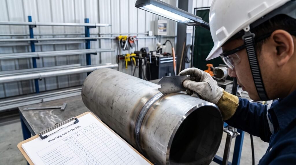
Lesson 3: Visual Inspection Checklist & ITP
Visual Inspection (VT) is the most effective, low-cost inspection method. It follows a structured Inspection and Test Plan (ITP) divided into three distinct stages:
1-Pre-Welding Stage (Fit-up Inspection):
a. Verify bevel angle, root face, and root gap dimensions.
b. Ensure joint faces are clean and free from rust, oil, paint, and moisture.
c. Confirm correct tack welding quality and alignment.
2. In-Process Stage (During Welding):
a. Monitor interpass temperature and preheat requirements.
b. Verify electrode class, diameter, and baking parameters.
c. Check amperage, voltage, and travel speed against the approved WPS.
3. Post-Welding Stage (Final Visual Inspection):
a. Measure weld throat thickness, leg length, and reinforcement height using a weld gauge.
b. Inspect for surface discontinuities such as cracks, porosity, spatter, and undercut.
c. Ensure complete slag removal and surface cleaning.
Lesson 4: NDT Methods in Welding Inspection
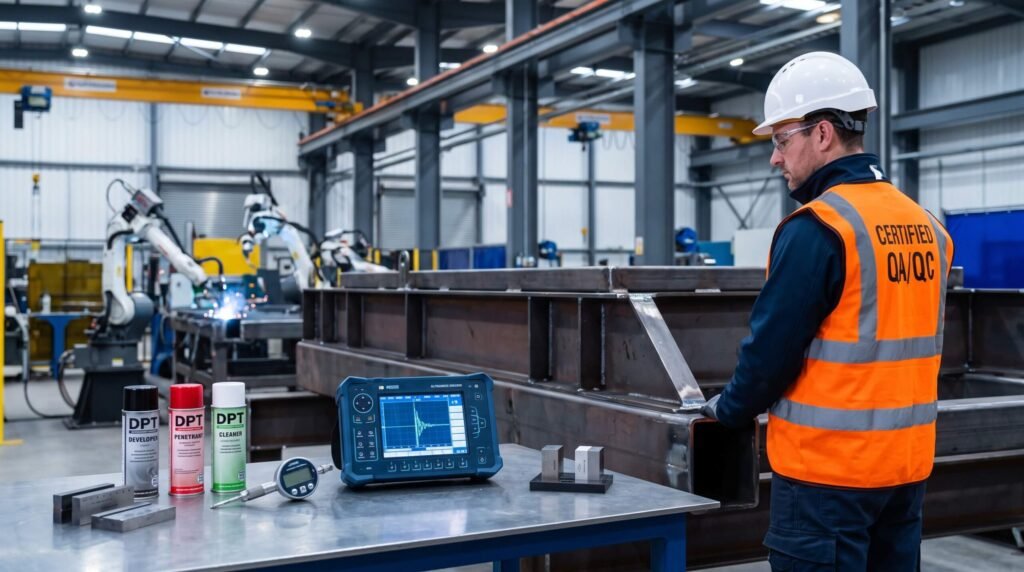
When visual inspection cannot detect internal or subsurface flaws, Non-Destructive Testing (NDT) techniques are implemented to evaluate the weld without damaging it.
Ultrasonic Testing (UT): High-frequency sound waves are beamed into the material. Internal flaws reflect the sound energy back to a transducer, producing a signal on a screen. Highly effective for detecting planar flaws like internal cracks and lack of fusion.
Radiographic Testing (RT): X-rays or Gamma rays pass through the weldment onto a digital detector or film. Density variations reveal internal defects like porosity, slag inclusions, and incomplete penetration.
Magnetic Particle Testing (MT): Applied exclusively to ferromagnetic materials. A magnetic field is induced in the part, and iron particles are applied. Surface and slightly subsurface flaws leak magnetic flux, attracting particles to reveal the defect.
Liquid Penetrant Testing (PT): Uses capillary action to draw a liquid dye into surface-breaking cracks. After cleaning the excess dye, a developer draws out the trapped dye to make invisible surface flaws clearly visible.
Lesson 5: QA/QC Documentation & Inspection Reports
In welding inspection, “what is not documented, is not done.” Proper documentation is the backbone of quality assurance.
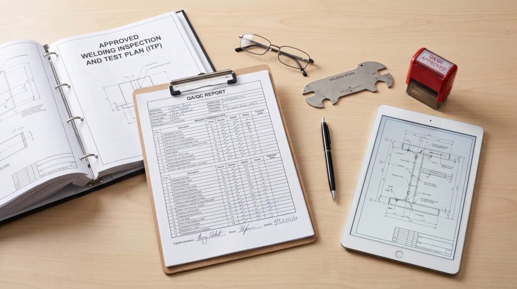
Inspection and Test Plan (ITP): The roadmap that outlines every inspection stage, hold points, and witness points from raw material to final dispatch.
Welding Procedure Specification (WPS) & PQR: The engineering documents that guide the welder on parameters like voltage, amperage, and heat input.
Welding Inspection Report: The final signed record containing dimensional checks, NDT results, and visual inspection data, handed over to the client for final sign-off.
Conculsion & Purpos of This Guide!
By understanding the responsibilities, defect identification steps, applicable codes (ASME, AWS, API), and NDT techniques outlined in this guide, professionals can clearly grasp the operational scope of QA/QC inspection. At Isotex Inspection Services, our goal is to empower industry professionals with actionable knowledge—helping you ensure that every welded joint meets the highest standards of safety, quality, and regulatory compliance.