

Chapter-1: Introduction to Ultrasonic Testing (UT) & Core Principles
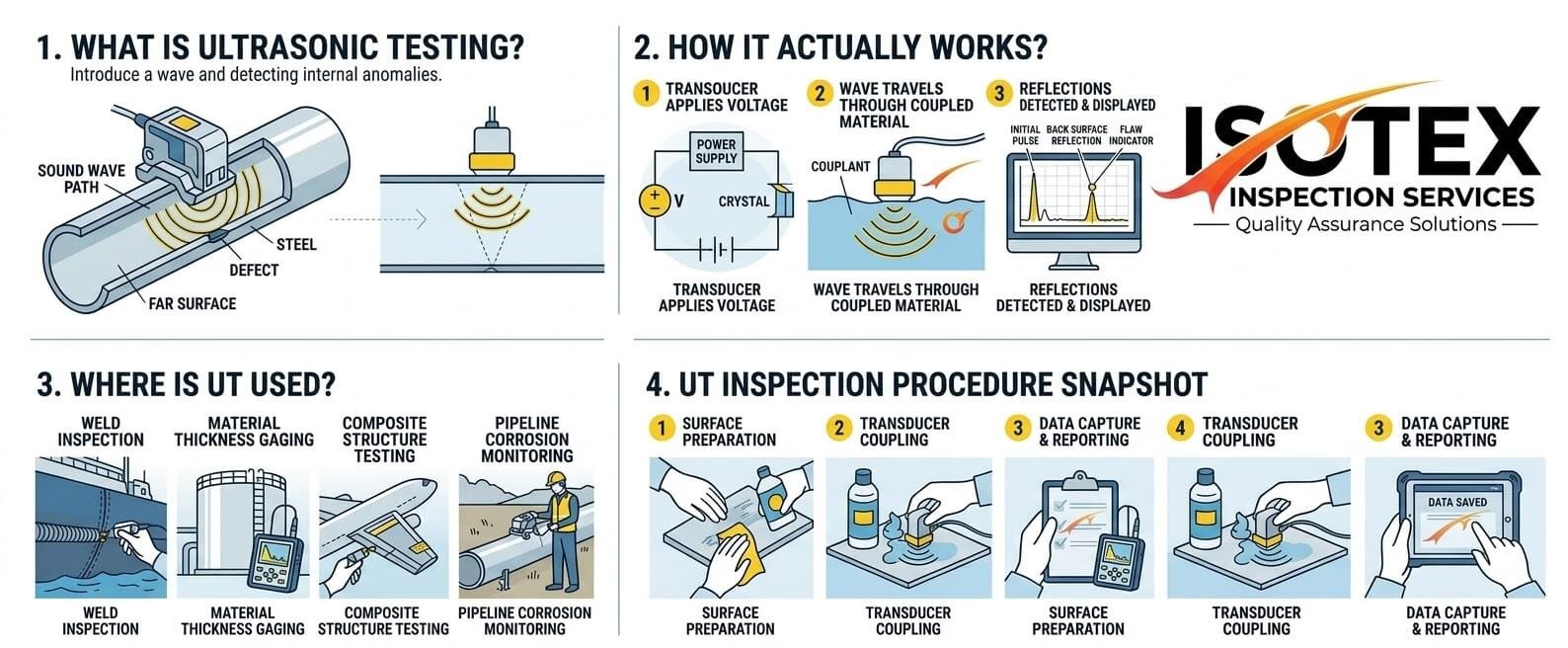
1. What is Ultrasonic Testing?
Welcome to this Ultrasonic Testing (UT) Level 2 Procedure Guide. Think of Ultrasonic Testing (UT) as an X-ray for industrial materials, but using sound instead of radiation. It’s a non-destructive testing (NDT) method where we send high-frequency sound waves usually between 0.5 MHz and 20 MHz—straight through a component. The best part? You get to inspect internal flaws and check material thickness without damaging the part in the slightest
2. How It Actually Works
The Probe (Transducer): You place a small probe on the surface. It converts electrical signals into high-frequency sound waves and shoots them into the material.
Travel & Reflection: As sound travels through solid metal, it moves cleanly until it hits a boundary—either the far wall of the material or a hidden flaw inside (like a crack or void). When it hits that boundary, part of the sound bounces right back.
Reading the Display (A-Scan): The probe catches those returning sound echoes and feeds them back to the machine. You’ll see them as spikes or “peaks” on the screen (known as an A-Scan display). By reading these spikes, you can pinpoint exactly where and how deep a flaw is.
3. Where Is It Used?
Pipelines & Welds: Spotting hidden internal cracks, lack of fusion, or slag trapped inside critical weld joints.
Wall Thickness Checks: Monitoring erosion and corrosion on live pipelines, storage tanks, and pressure vessels.
Forgings & Castings: Catching internal shrinkage, voids, and inclusions in heavy machinery parts before they fail on site.
4. The Pros & Cons
Why inspectors love it:
Deep penetration: It can punch through thick steel sections that other methods struggle with.
One-sided access: You only need to touch one side of the pipe or plate to get an accurate read.
Instant answers & safer sites: You get real-time feedback with zero radiation hazard, meaning no site shutdowns like radiography requires.
Where it gets tricky:
Surface prep matters: Rough, dirty, or heavily scaled surfaces will block the sound. You also always need a liquid medium (couplant) between the probe and metal.
Skill-dependent: The equipment doesn’t make decisions—the operator does. Interpreting the screen takes solid training and hands-on experience.
5. Field Procedure Snapshot
Step 1 – Surface Check: Clean off grease, loose rust, and paint flakes. Sound waves hate air gaps.
Step 2 – Apply Couplant: Dab a bit of gel, oil, or paste on the metal to help sound transfer smoothly from the probe into the part.
Step 3 – Read the Screen: You’ll see a spike at the start (Initial Pulse) and a spike at the back end (Backwall Echo). Any unexpected peak popping up in between those two markers usually means you’ve hit a flaw.
Chapter 2: UT Equipment, Transducers & Calibration Guidelines
Understanding your equipment is just as critical as reading the echoes on the screen. Before you ever touch a weld or pipe section, you need to know how your tools work and how to set them up for accurate inspection results.

1. Key Ultrasonic Testing Equipment Components:
Every standard UT setup relies on three main physical elements:
The Flaw Detector Unit: The central display machine that generates electrical pulses and plots returning signals on an A-scan display.
Probes (Transducers): Devices containing piezoelectric crystals that convert electrical energy into sound waves (and vice versa).
Couplant: A liquid or gel (such as oil, glycerin, or water-based paste) placed between the probe and the test piece. It eliminates air gaps, allowing sound energy to pass smoothly into the material.
2. Types of Probes and Their Field Uses:
Choosing the right probe depends entirely on the type of component you are inspecting:
Normal Beam (Straight Beam) Probes:
How they work: Send longitudinal sound waves straight down at 70° into the material.
Primary uses: Thickness measurements, detecting lamination flaws in plates, and inspecting flat forgings or castings.
Angle Beam Probes:
How they work: Use an internal plastic wedge to direct shear waves into the material at specific angles (typically 45°, 60°, or 70°).
Primary uses: Weld inspections, where you need the sound wave to bounce off the bottom surface to catch side-wall lack of fusion or root cracks.
3. Step-by-Step Equipment Calibration:
Calibration ensures your readings are reliable, repeatable, and compliant with inspection standards like ASME or AWS.
Step 1 – Visual & Mechanical Check: Inspect your probe cable for damage, clean the probe face, and verify your display machine is fully charged.
Step 2 – Zero Offset Adjustment: Place your probe on a standard reference block (like an IIW V1 or V2 block) to adjust the machine’s internal delay, ensuring the sound entry point is zeroed out.
Step 3 – Velocity Calibration: Set the sound velocity in the unit to match your material (for carbon steel, longitudinal wave velocity is roughly 5920 m/s, and shear wave velocity is roughly 3250 m/s).
Step 4 – Range Calibration: Adjust the sweep scale using the known thickness steps on your calibration block so the peaks align exactly with the physical dimensions marked on the block.
Step 5 – DAC (Distance Amplitude Correction) Curve Construction: For angle beam testing, scan side-drilled holes at various depths on a calibration block to draw a reference line across the screen. This compensates for natural sound attenuation over distance.
4. Inspector’s Field Tip:
Always re-check your calibration at least once every 4 hours, whenever you change probes/cables, or if the ambient temperature changes significantly on site. A small drift in calibration can mean missing a critical defect or calling a false indication.
Chapter 3: Surface Preparation, Weld Scanning & Field Procedure Guidelines
Following a structured UT Level 2 Procedure Guide is essential when dealing with field conditions…”
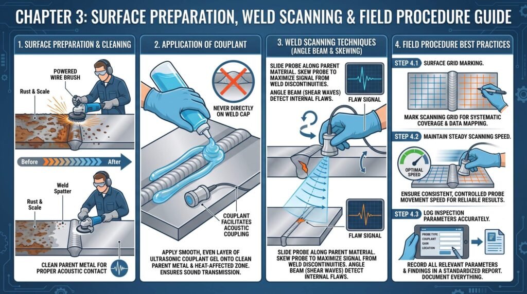
Having reliable equipment and a sharp calibration curve won’t matter if your scanning technique on site is flawed. Field conditions present real-world challenges rust, rough weld beads, and tight access that directly affect your sound beam. This chapter outlines the hands-on steps as detailed in our UT Level 2 Procedure Guide to perform a clean, accurate UT inspection.
1. Essential Surface Preparation
Proper surface preparation is the first critical phase of any UT Level 2 Procedure Guide…
Sound waves at high frequencies cannot bridge air gaps. Loose scale or debris will scatter the acoustic energy before it even enters the material.
Cleaning Width: Wire-brush or grind the parent metal on both sides of the weld. Clean a strip equal to at least two skip distances (usually 3 to 4 inches) back from the weld centerline.
Surface Condition: Remove loose rust, mill scale, heavy paint flakes, weld spatter, and oil. Smooth, tightly adhering paint up to 0.1 mm thick is generally acceptable, but thick protective coatings must be factored into your calibration or removed entirely.
Base Metal Check (Lamination Scan): Before inspecting the weld, run a straight-beam probe over the scanning zone on the parent metal. This checks for internal laminations or wall thinning that could block your angle beam from reaching the weld seam.
2. Scanning Movement & Coverage Techniques
To ensure 100% volumetric coverage of the weld and heat-affected zone (HAZ), your probe movement must be structured and deliberate.
Traversing (Zig-Zag) Motion: Move the angle probe back and forth toward and away from the weld centerline while advancing slowly along the length of the joint.
Scanning Pitch (Overlap): Ensure each continuous pass overlaps the previous one by at least 10% to 15% of the transducer element width. Never leave un-scanned gaps.
Probe Rotation (Swiveling): Slightly swivel the probe (10°, 15°) as you traverse. This slight angle angling helps catch misaligned flaws like sidewall lack of fusion that aren’t perfectly parallel to the weld seam.
Two-Sided Inspection: Whenever possible, scan the weld seam from both sides (Side A and Side B) and from both top and bottom surfaces to cover all potential reflection angles.
3. Understanding Skip Distance and Beam Paths
Angle beam testing relies on sound reflecting off the inside surface (ID) of the pipe or plate to inspect the upper half of the weld joint.
Half-Skip (Direct Path): The sound travels directly from the probe to the bottom surface (ID) of the plate. This path primarily tests the lower root section of the weld.
Full-Skip (Indirect Path): The sound bounces off the bottom surface and travels upward to hit the top surface (OD) of the plate. This path inspects the middle and crown sections of the weld joint.
4. Step-by-Step Field Execution Checklist
Apply Couplant: Apply an even layer of paste, gel, or heavy oil along the prepped scanning path.
Set Base Gain: Set your reference level gain established during your DAC calibration. Add your designated “scanning gain” typically +6 dB to +12 dB to ensure small, deep flaws pop up clearly during the sweep.
Execute the Scan: Progress systematically down the weld length, maintaining steady, moderate hand pressure on the probe.
Mark Indications: Whenever an echo breaks your reference level on the screen, halt probe movement, drop back to reference gain, and pinpoint the defect’s location, depth, and length
Chapter 4: Flaw Interpretation, Acceptance Criteria & Report Writing
Scanning the material and picking up signals is only half the job. The real core of a Level II inspector’s responsibility lies in evaluating those signals distinguishing real defects from geometry, comparing them against code standards, and producing a clear, defensible report.
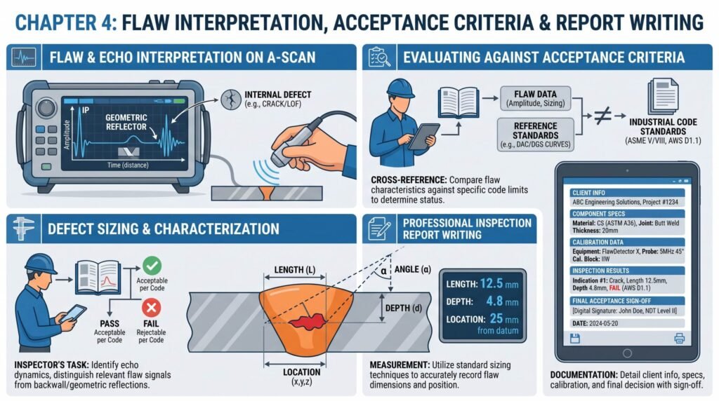
1. Distinguishing Real Flaws from Geometric Echoes
Not every peak on your A-scan screen represents a structural defect. Before logging a flaw, you must rule out false calls caused by the component’s shape.
Geometric Reflections: Extra echoes often arise from backing bars, weld root reinforcement, surface ripples, or counterbores. You can verify these by measuring the exact beam path distance or touching the surface with a damp finger to damp the signal.
Planar Flaws-Cracks & Lack of Fusion: These display sharp, narrow, highly directional peaks. Rotating or moving the probe slightly will cause the echo height to drop off rapidly.
Volumetric Flaws-Porosity & Slag Inclusions: Porosity shows up as a cluster of small, fluctuating peaks. Slag inclusions yield broader, slightly ragged echoes that remain relatively stable as you move around them.
2. Evaluating Flaw Severity (Signal Amplitude vs. Length)
When a legitimate flaw echo exceeds your reference level, you must evaluate both its signal amplitude and its physical length:
Sizing the Depth and Location: Use your calibrated screen scale to calculate the depth (d) and surface distance (s) from the probe index point to the reflector.
6 dB: Drop Method for Flaw Length: Move the probe along the length of the flaw until the signal reaches its maximum peak. Slide the probe sideways parallel to the weld until the peak drops by 50% (which is a -6 dB drop). Mark this position on the steel. Move the probe in the opposite direction until the peak drops by -6 dB again and mark the second point. The distance between these two marks is the operational length of the flaw.
3. Applying Code Acceptance Criteria (ASME Sec V/VIII vs. AWS D1.1)
An inspector does not guess whether a defect passes or fails; you must apply the governing code:
ASME Section VIII (Pressure Vessels): Focuses heavily on signal amplitude relative to the DAC curve. Any crack, lack of penetration, or lack of fusion is strictly unacceptable regardless of size. Other linear indications are rejected if their amplitude exceeds the DAC curve and their length exceeds code limits based on material thickness.
AWS D1.1 (Structural Welding): Uses a specific rating system (d = a – b – c) comparing the indication rating (a). zero reference level (b), and attenuation factor (c). The resulting severity class (Class A, B, C, or D) dictates whether the weld passes or requires repair.
4. Writing a Professional Inspection Report
Your report is a legal document that proves compliance. A complete UT Level II report must contain:
Header Details: Client name, project location, component ID, material grade, and thickness
Equipment Specs: UT machine serial number, probe frequency, angle, crystal size, cable type, and calibration block used.
Procedure Reference: Written UT procedure number, revision date, and applicable code (e.g., ASME Sec V Art 4).
Flaw Log Table: Detailed breakdown listing indication number, location (weld distance), depth, length, peak amplitude (% DAC), and final status (Accept / Reject).
Sign-off: Inspector’s full name, NDT Level II certification standard (ASNT SNT-TC-1A / ISO 9712), signature, and date.
Final Thoughts: Elevating NDT Standards Through Accessible Education
Ultrasonic Testing is more than just operating a machine, it is a critical safety discipline that protects infrastructure, industries, and human lives. Mastering UT Level II concepts requires a blend of core acoustic physics, precise equipment calibration, methodical weld scanning, and strict adherence to international codes like ASME and AWS.

At Isotex Inspection Services (IIS), our goal behind publishing this comprehensive UT Level 2 Procedure Guide is to make high-quality, field-ready Non-Destructive Testing knowledge freely accessible to aspiring inspectors, quality control technicians, and engineering students worldwide. Whether you are using this UT Level 2 Procedure Guide to prepare for ASNT certification exams or refining your daily inspection techniques on site, clear, practical education builds a safer industrial future.