
Introduction!
Concave and convex fillet welds can have the same leg length and still behave very differently in service. A convex weld bulges outward, while a concave weld curves inward. In oil and gas fabrication, such as pipe supports, skid frames, vessel attachments, and structural steel, this profile affects fatigue life, crack risk, and acceptance during inspection.
This article explains how concave and convex fillet welds are produced and checked, how they appear on drawings, and what AWS D1.1 and API 1104 say about them. It also covers the convex vs concave weld question that many welders and inspectors ask on site.
Fillet Weld Type vs. Weld Profile
These two terms are often confused.
- Fillet weld is the weld type. It is the roughly triangular weld used in T-joints, lap joints, and corner joints.
- Flat, convex, and concave describe the weld profile, which is the shape of the weld face.
So a fillet weld can have a flat, convex, or concave profile. Also note that “flat position” (1F or 1G) is a welding position. It describes how the weld is made, not what it looks like, so it is a different idea from a flat profile.
What Are Concave and Convex Welds?
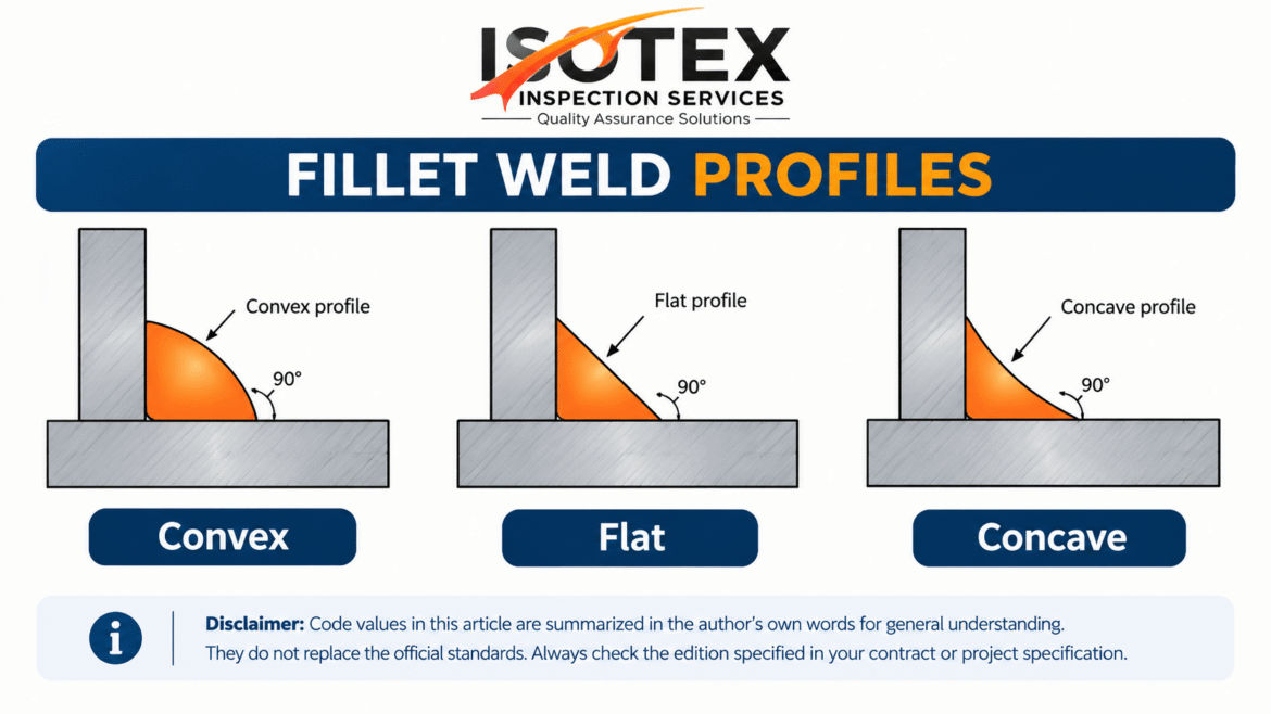
Convex Weld
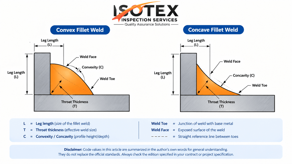
The face bulges outward and carries extra metal above the straight line joining the two weld toes. The toe is the point where the weld metal meets the base metal.
Concave Weld
The face curves inward, below the straight line between the toes. It gives a smooth blend into the plates.
Flat Weld Profile
The face lies almost on the straight line between the toes. It is often treated as the reference shape.
How Are the Profiles Produced?
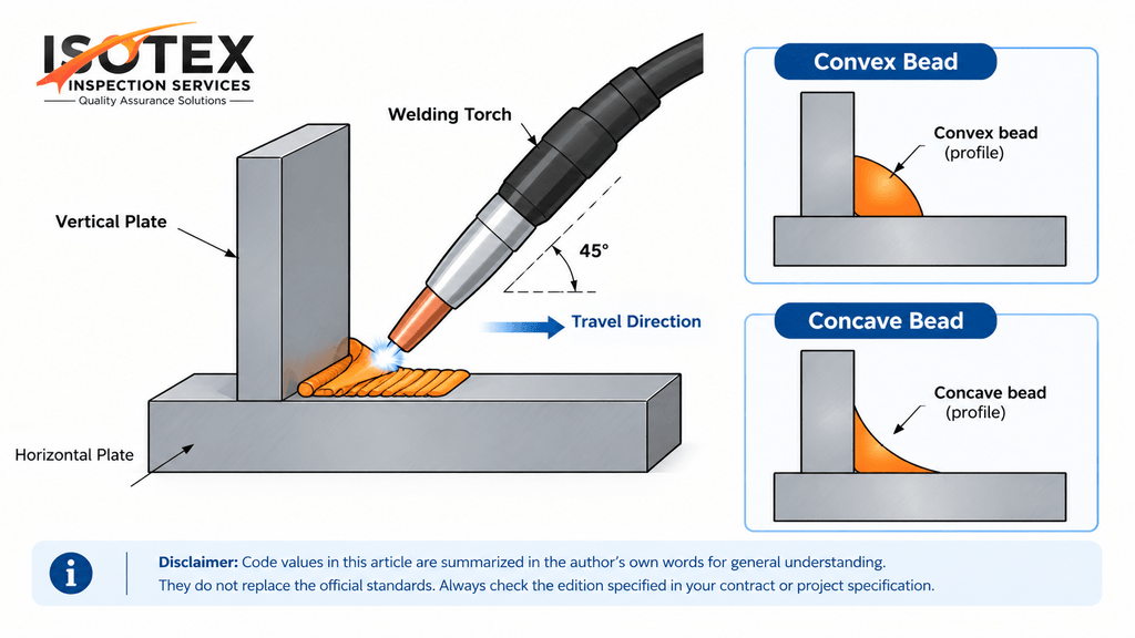
The profile is controlled by technique and welding parameters, not by a special process. SMAW, GMAW, FCAW, and SAW can all produce either shape.
Producing a Convex Profile
- Use a slower travel speed so more metal is deposited per unit length.
- Use lower arc voltage, which keeps the weld pool narrow and tall.
- Use a steeper electrode angle with little weaving.
- Deposit a larger bead in a single pass.
Producing a Concave Profile
- Use a faster travel speed or higher arc voltage so the pool spreads and flattens.
- Hold the electrode at about 45 degrees to each plate.
- Use a controlled weave or several smaller passes.
- Make sure both toes are wetted well.
Advantages and Disadvantages
Convex Welds
Advantages
- More weld metal, so a small throat shortfall is less likely.
- More forgiving for less experienced welders.
- In some restrained joints, it can resist shrinkage cracking better.
Disadvantages
- The extra metal does not add design strength, because strength is based on the effective throat.
- The sharp toe angle causes stress concentration and lowers fatigue life.
- It needs more filler metal, time, and cost.
- It is rejected when convexity exceeds the code limit.
Concave Welds
Advantages
- Smooth toe transition and lower stress concentration.
- Better fatigue behavior when the weld is correctly sized.
- Less filler metal and less distortion.
- Easier to inspect and coat.
Disadvantages
- For the same leg length, the throat is smaller, so the weld can end up undersized.
- Higher risk of centerline shrinkage cracks in restrained or thick joints.
- It needs more skill to achieve both the correct leg size and throat.
Code Limits: AWS D1.1
AWS D1.1/D1.1M:2025, Structural Welding Code – Steel [1], is the main reference for structural steel such as pipe racks, skid frames, and support steel. It accepts fillet welds that are flat, slightly convex, or slightly concave, as long as the required size and throat are met.
Convexity Limits
Table 1: Maximum fillet weld convexity (AWS D1.1)
| Weld face width (W) | Maximum convexity (C) |
|---|---|
| Up to 5/16 in (8 mm) | 1/16 in (2 mm) |
| Over 5/16 in to under 1 in (25 mm) | 1/8 in (3 mm) |
| 1 in (25 mm) or more | 3/16 in (5 mm) |
Note: These values come from the visual inspection criteria of AWS D1.1 and have stayed consistent across recent editions. Table and clause numbers change between editions, so confirm them in your edition before quoting. Metric values are rounded. A project specification or a cyclically loaded structure may set stricter limits.
Concavity
D1.1 does not give one fixed concavity depth. The rule is based on the result: the weld must still meet the specified size and effective throat. A deeply concave weld that reduces the throat below the required value is rejected as undersized
Other Related Visual Limits
Table 2: Related visual acceptance limits (AWS D1.1, summarized)
| Feature | General requirement |
|---|---|
| Cracks, lack of fusion, overlap | Not acceptable |
| Undercut (statically loaded, material under 1 in) | About 1/32 in (1 mm) maximum, with limited exceptions |
| Undercut (cyclically loaded, primary tension members) | About 0.01 in (0.25 mm) maximum |
| Undersize fillet leg | Allowed only over a limited part of the weld length (about 10 percent), and the allowed shortfall depends on nominal size |
Note: These are summarized in the author’s own words and rounded. Undercut and undersize rules depend on material thickness, load type, weld length, and joint type, which a short table cannot show in full. Read the complete acceptance table in the current edition before accepting or rejecting a weld.
Code Limits: API 1104
API 1104, Welding of Pipelines and Related Facilities, 22nd Edition [2], is written mainly for pipeline girth welds. Its scope also covers fillet and branch welds on fittings, sleeves, and similar components. However, it does not provide a fillet weld convexity table comparable to AWS D1.1. For fillet welds, size and profile limits are normally taken from the project specification or the design drawing.
How Fillet Welds Are Handled
Fillet welds under API 1104 are qualified through a procedure test, usually a fracture (break) test and macro examination. The weld is expected to show good fusion, no cracks, and a workmanlike appearance.
Profile Rules for Butt Welds (Closest Equivalent)
Table 3: Butt weld profile requirements (API 1104, 22nd Edition, summarized)
| Feature | General requirement |
|---|---|
| Weld crown (external reinforcement) | Must not be below the pipe surface; height normally limited to about 1/16 in (1.6 mm) |
| External concavity | Crown must not fall below the adjacent pipe surface |
| Internal concavity | Accepted only if radiographic density and minimum thickness criteria are met |
| Undercut | Limited by depth (about 1/32 in or 12.5 percent of wall thickness, whichever is smaller) and by length, depending on the inspection method |
Note: API 1104 acceptance limits depend on the inspection method (visual, radiographic, or other) and on whether the weld is manual, mechanized, or assessed by engineering critical assessment (ECA) in Appendix A. Crown height and some limits may differ between editions or project specifications. Verify every value against the 22nd Edition before use.
Practical Meaning
For a structural attachment, follow the D1.1 convexity table. For a pipeline girth weld, you are controlling crown height, undercut, and internal concavity under API 1104. If a pipeline job includes fillet welds, the project specification should state the size and profile limits clearly.
Which Edition Applies?
Codes are revised every few years. AWS D1.1 follows a five-year cycle [1], and API published the 22nd Edition of 1104 in July 2021, with Errata 1 in September 2023 [2]. Regulations can lag behind the newest edition. For example, US PHMSA’s pipeline regulations have incorporated the 21st Edition (2013) of API 1104 [5]. Always use the edition named in the contract, client specification, or regulation.
How Is the Profile Tested and Inspected?
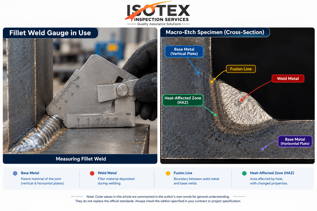
Profile is checked mainly by visual inspection (VT) using a fillet weld gauge. This is a thin template that reads leg length, throat, and convexity or concavity. Supporting methods are:
- Macro-etch test: a cross-section is cut, polished, and etched so the weld shape, penetration, and fusion lines are visible.
- Fillet weld break test: the weld is broken open to check fusion and internal defects. It is common in welder and procedure qualification.
- Magnetic particle (MT) or dye penetrant (PT) testing: used to find surface cracks, especially at the toes.
Welding Symbols for Weld Contour
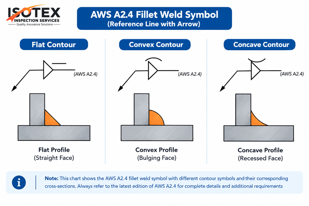
On drawings, the profile is shown by a contour symbol placed on the weld symbol, together with a finish letter if finishing is required. These follow AWS A2.4 [3].
Table 4: Contour symbols and finish letters (AWS A2.4) [3]
| Contour | Symbol shape |
|---|---|
| Flat | Short straight line |
| Convex | Arc bulging outward |
| Concave | Arc curving inwar |
| Finish letter | Method |
|---|---|
| C | Chipping |
| G | Grinding |
| H | Hammering |
| M | Machining |
| P | Peening |
| R | Rolling |
Note: Symbols follow AWS A2.4. Some projects use ISO 2553 symbols, which look different. Check which symbol standard the drawing set uses.
For example, a convex symbol with the letter G tells the welder to grind the weld to a convex contour.
Why Defining the Profile Properly Matters.
- It avoids disputes. Fabricator, inspector, and client may each read “acceptable shape” differently. A written profile and size remove the argument.
- It protects strength. Throat thickness, not appearance, defines capacity.
- It improves fatigue life. Where loading is cyclic, requiring a flat or slightly concave toe blend can extend service life.
- It reduces rework and cost. It prevents over-welding and undersized welds.
- It supports code compliance with AWS D1.1 [1], API 1104 [2], ASME B31.3 [4], and project specifications.
- It prevents confusion between fillet profile and butt weld terms such as reinforcement and root concavity.
Practical Tips for Welders and Inspectors.
- Confirm the required leg size and minimum throat before welding.
- Measure with a calibrated gauge, never by eye.
- Check both toes for undercut and lack of fusion.
- Follow the project specification if it is stricter than the code.
- Keep inspection records for traceability.
Conclusion!
A convex weld adds metal but not strength, and it can reduce fatigue life. A concave weld blends smoothly but can lose throat if overdone. Under AWS D1.1, convexity has clear numerical limits and concavity is judged by the remaining throat. Under API 1104, the focus is on butt weld crown, undercut, and internal concavity, so fillet profile limits usually come from the project specification. Verify with a gauge, use the edition required by your contract, and show the requirement clearly on the drawing with the correct contour symbol.
References.
- American Welding Society. AWS D1.1/D1.1M:2025, Structural Welding Code – Steel, 23rd Edition. Miami, FL: AWS, 2025.
- American Petroleum Institute. API Standard 1104, Welding of Pipelines and Related Facilities, 22nd Edition, July 2021, including Errata 1 (September 2023). Washington, DC: API.
- American Welding Society. AWS A2.4, Standard Symbols for Welding, Brazing, and Nondestructive Examination (latest edition).
- ASME. ASME B31.3, Process Piping (latest edition).
- U.S. Department of Transportation, PHMSA. Letter from API on Welding Procedure and Welder Qualifications using API Standard 1104, August 2025.
Edition note: Standards are revised periodically. The editions above were the latest found at the time of writing (October 2026). Check the publisher’s website for any newer edition or amendment before relying on this article.
FAQ’S
1. What is the difference between convex and concave welds?
A convex weld has a face that bulges outward, above the straight line between the two weld toes. A concave weld has a face that curves inward, below that line. Both are fillet weld profiles. Convex carries extra metal, while concave blends smoothly into the base plates.
2. Which is better, a convex or a concave fillet weld?
Neither is better in every case. A convex weld adds metal, but design strength is based on the specified throat, so the extra bulge is not counted. A concave weld reduces stress concentration at the toes but can lose throat if overdone. A flat or slightly concave weld with correct size is generally preferred.
3. What is the maximum convexity allowed for a fillet weld?
Under AWS D1.1, allowed convexity depends on weld face width. It is about 1/16 in (2 mm) for faces up to 5/16 in, 1/8 in (3 mm) for faces between 5/16 in and 1 in, and 3/16 in (5 mm) for faces of 1 in or more. Verify against your current edition [1].
4. How do you check convexity and concavity in a fillet weld?
Inspectors use visual inspection with a fillet weld gauge. The gauge is placed against the weld and reads leg length, throat, and convexity or concavity. For more detail, a macro-etch test shows the weld shape and fusion lines, and MT or PT finds surface cracks at the toes.
5. What are the weld symbols for convex and concave contours?
On a drawing, the contour symbol sits on the weld symbol. A flat contour is a short straight line, a convex contour is an arc bulging outward, and a concave contour is an arc curving inward. A finish letter such as G (grinding) can be added. These follow AWS A2.4 [3].